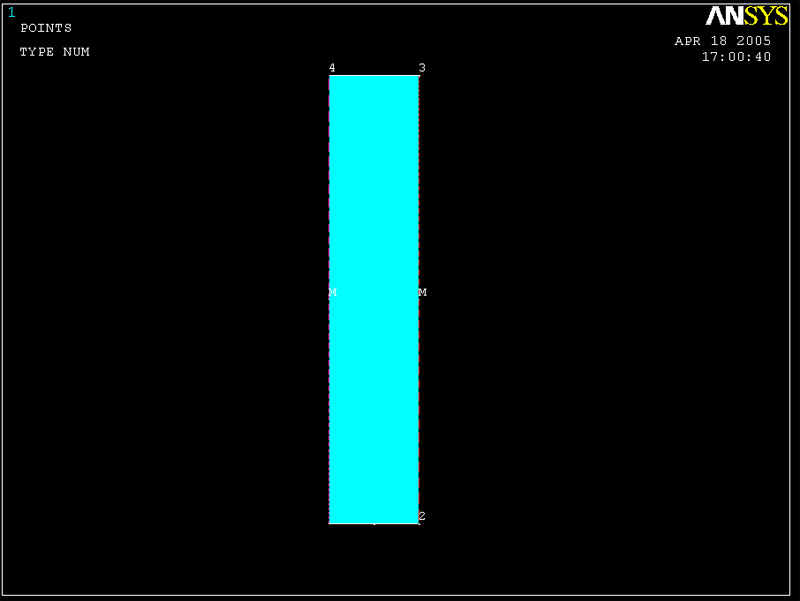
3. Mesh the Object
We need to mesh
the following:
Line A and C to have 50 divisions,
Line B to have 10 divisions,
Line E and D to have 5 divisions.
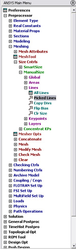
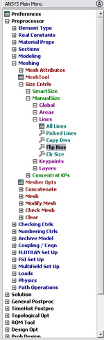
MAIN MENU -> Preprocessor
PREPROCESSOR -> -Meshing -Size Contrls
SIZE
CNTRLS -> -Line
-Picked Lines
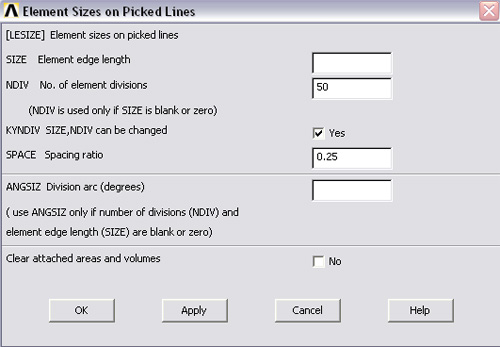
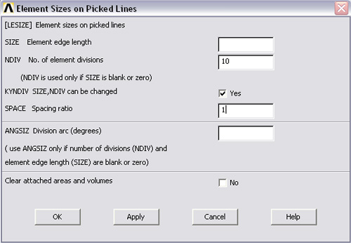
ELEMENT SIZE ON PICKED LINES -> Click on line A and C of the
part.
ELEMENT SIZE ON PICKED LINES -> Click OK.
ELEMENT SIZE ON PICKED LINES -> Enter 50 in the NDIV box, and 0.25 in
the spacing ratio box then click OK.
Now
you can see that line A and C are meshed.
To
mesh
line B, enter in 10 in NDIV box and 1 in the spacing ratio box.
SIZE
CNTRLS -> -Line -Picked Lines
ELEMENT SIZE ON PICKED LINES -> Click on line B (top of the plate).
ELEMENT SIZE ON PICKED LINES -> Click OK.
ELEMENT SIZE ON PICKED LINES -> Enter 10 in the NDIV box and 1 in SPACE
boc, then click OK.
To mesh
line D and E, enter in 5 in NDIV box and 1 in the spacing ratio box
SIZE
CNTRLS -> -Line -Picked Lines
ELEMENT
SIZE ON PICKED LINES -> Click on line D and E (the bottom of the
plate).
ELEMENT
SIZE ON PICKED LINES -> Click OK.
ELEMENT
SIZE ON PICKED LINES -> Enter 5 in the NDIV box and 1 in SPACE
boc, then click OK.
However, we want finer mesh close to the base. In this case line C has
to be fliped. We use the command, FLIP BIAS
Then click on the line which you want to flip, which is in this case, line
C.
Click OK. The meshed line will be flipped.

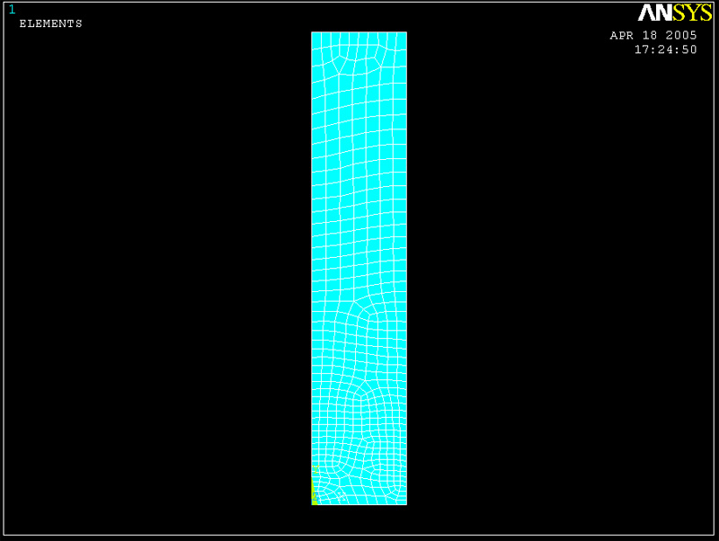
Now the meshed lines should look similar to the image below. Then we are ready
to mesh the area.
Use the following command:
MAIN MENU -> Preprocessor
PREPROCESSOR -> -Meshing -Mesh
MESH
-> -Area
- Free
MESH AREAS -> Click on the plate. It will change color. Click OK.
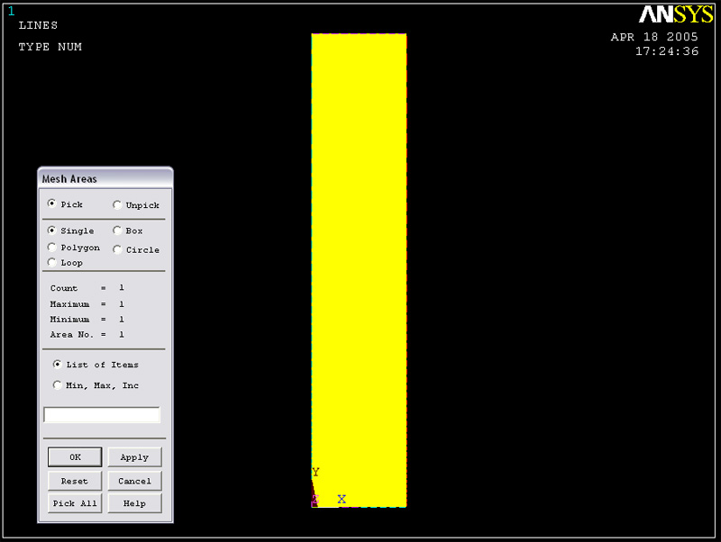
Wait
for ANSYS to mesh the rectangle. The correct meshed plate should look similar
to the one below.